Modbus Vibration Monitor - nRF9160 DK Follow-Along Guide
This follow-along guide shows how to build your own Modbus Vibration Monitor using widely available off-the-shelf development boards from our partners. We call this Follow-Along Hardware, and we think it's one of the quickest and easiest ways to get started building an IoT proof-of-concept with Golioth.
You will learn how to assemble the hardware, flash a pre-built firmware image onto the device, and connect to the Golioth cloud in minutes. The follow-along hardware runs the same open-source firmware as the custom Golioth hardware described in the project page, and we provide instructions on how to build it yourself if you want to make changes for your specific application.
Build the hardware
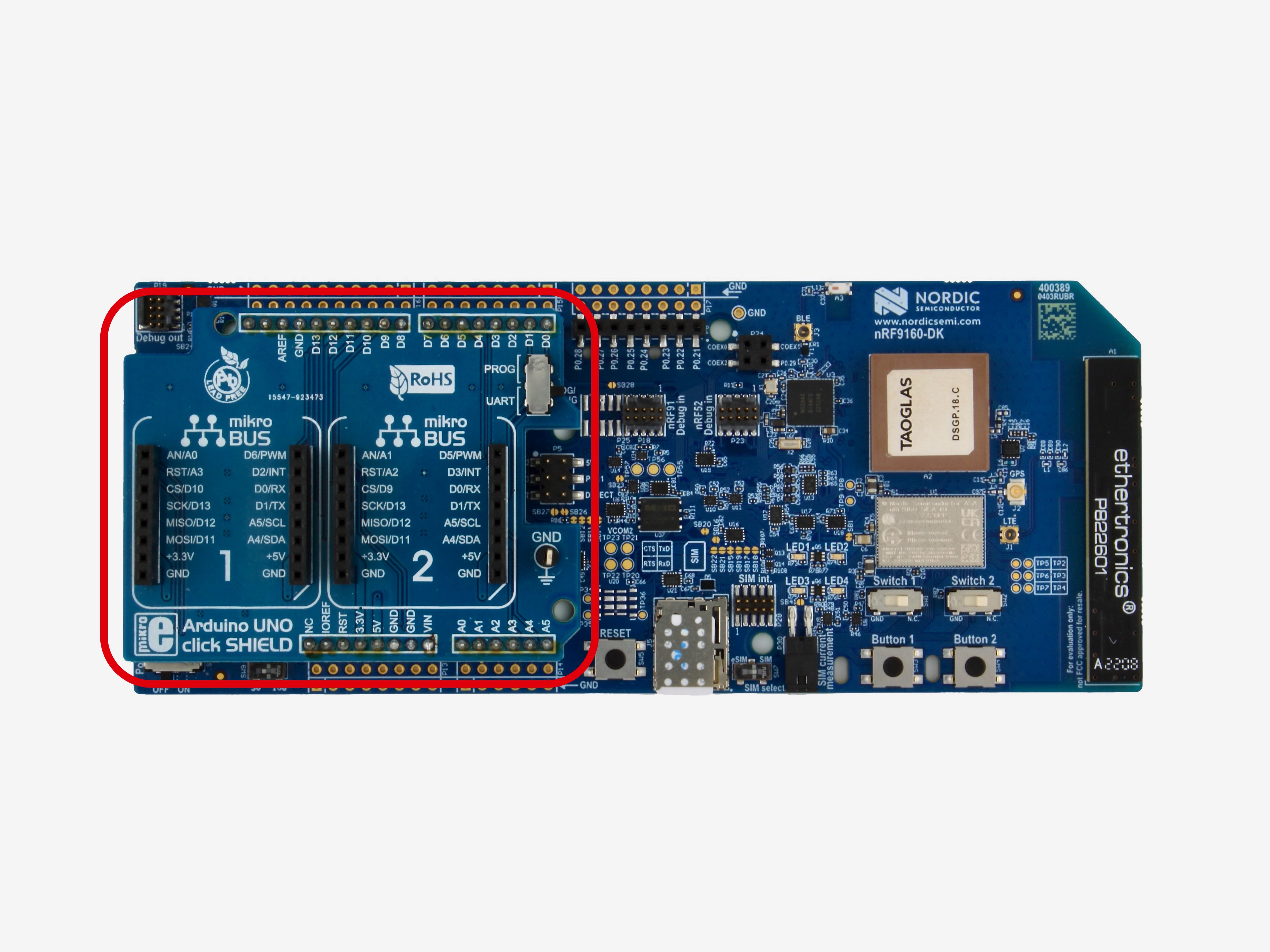
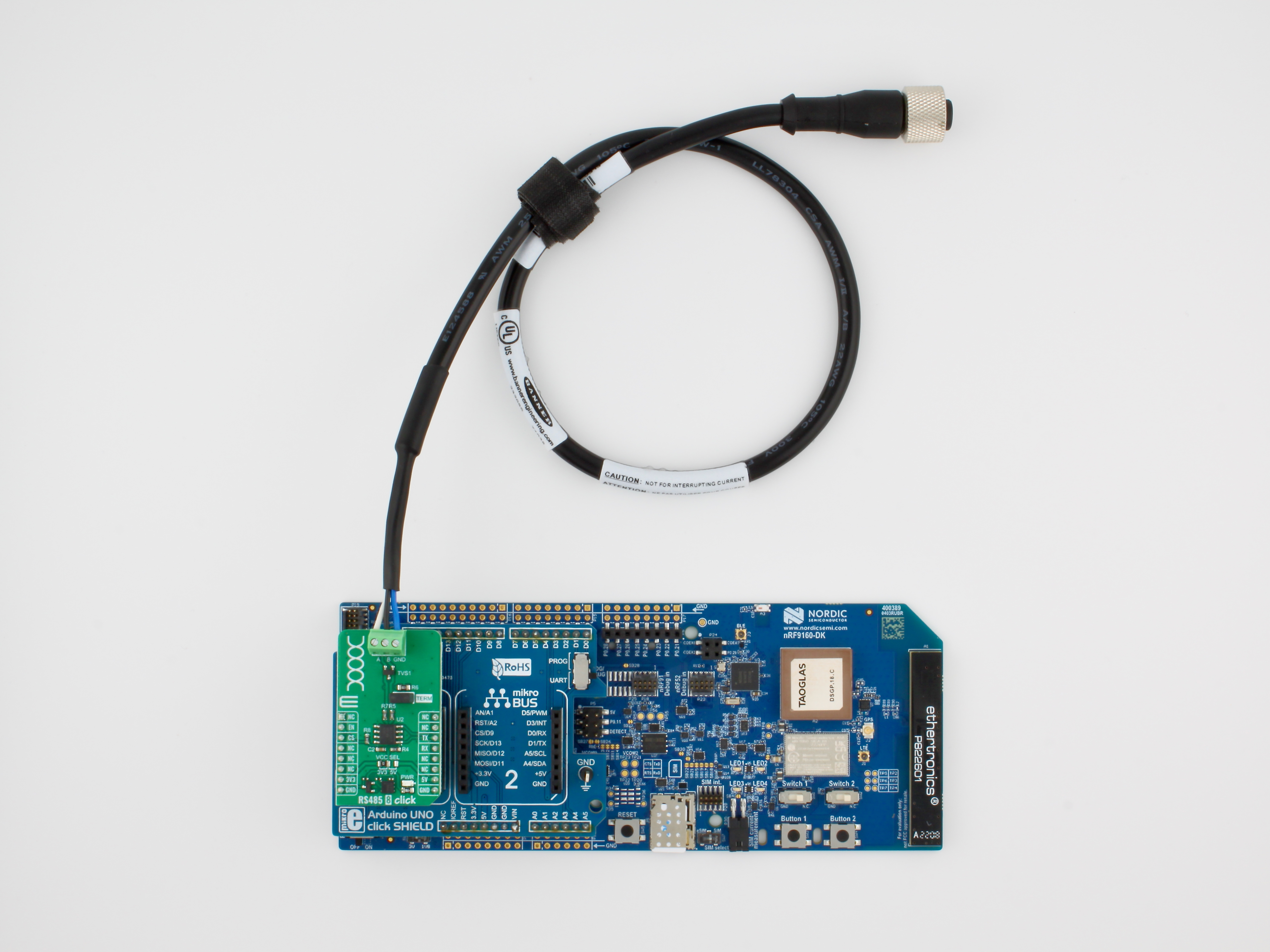
The follow-along hardware is based on the Nordic nRF9160 DK cellular IoT development board for LTE-M & NB-IoT. We use an Arduino UNO click shield to add two mikroBUS™ host sockets to the nRF9160 DK board.
The mikroBUS Click sockets are populated with one off-the-shelf MikroE Click sensor board:
- RS485 8 Click board with a THVD1426 RS-485 transceiver
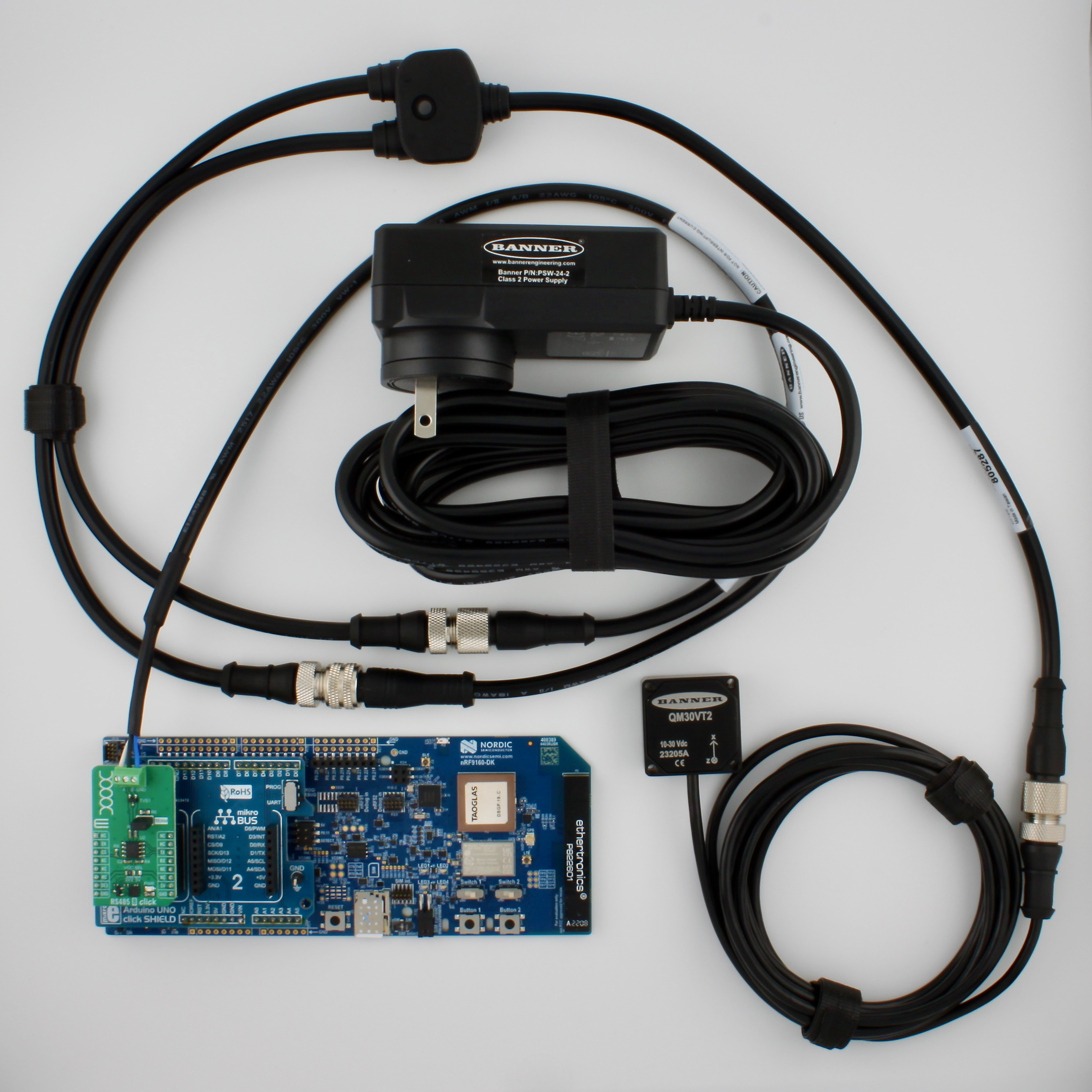
Device Photos
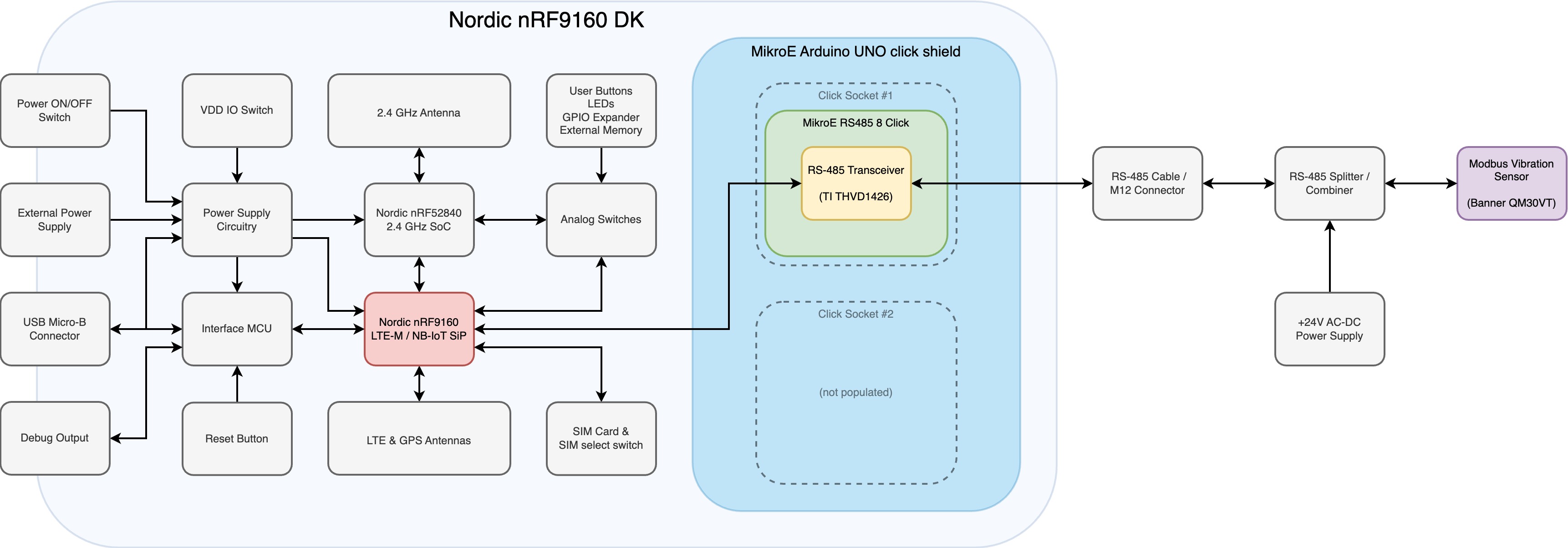
Hardware Block Diagram
Parts List
To assemble the follow-along hardware, you will need to purchase the following parts:
| Quantity | Manufacturer Part Number | DigiKey Part Number | Description |
|---|---|---|---|
| 1 | NRF9160-DK | NRF9160-DK-ND | Nordic nRF9160 DK Cellular IoT development kit |
| 1 | GL1-100 | 1887-GL1-100-ND | Hologram Hyper eUICC IoT SIM card |
| 1 | MIKROE-1581 | 1471-1341-ND | MikroE Arduino UNO Click shield adapter board |
| 1 | MIKROE-5752 | 1471-MIKROE-5752-ND | MikroE RS485 8 Click board |
| 1 | SPC02SYAN | S9001-ND | 2-position shunt jumper connector 0.100" (2.54mm) |
| 1 | QM30VT2 | 2170-QM30VT2-ND | Banner Modbus temperature & vibration sensor |
| 1 | MQDC1-501.5 | 2170-MQDC1-501.5-ND | M12 5-pin straight female cable with flying leads |
| 1 | PSW-24-2 | 2170-PSW-24-2-ND | 24V 48W AC/DC external wall mount power adapter |
| 1 | CSB-M1251FM1251M | 2170-CSB-M1251FM1251M-ND | M12 splitter 5-pin cable assembly (M12F to M12M and M12M connectors) |
Assembly Instructions
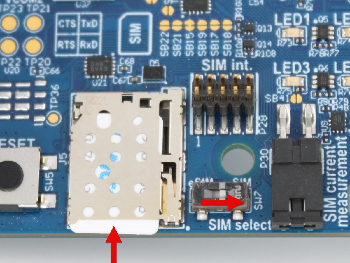
Step 1 - Install SIM card
With the board powered off, insert the SIM card into the socket and make sure the "SIM select" switch (SW7) is set to "SIM".
For more information about how to use this switch to select between the SIM card socket and the Embedded SIM (eSIM), see the Nordic SIM and eSIM documentation.
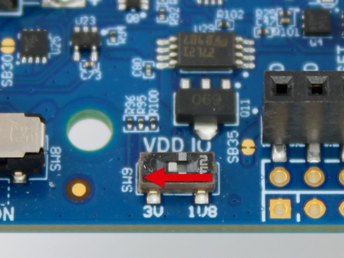
Step 2 - Set VDD IO voltage
Set switch SW9 (located next to the power switch) to 3V to set the VDD IO voltage to +3V.
For more information about how to use this switch to set the VDD supply rail, see the Nordic VDD supply rail documentation.
Step 3 - Install Arduino UNO click shield
Install the Arduino UNO click shield into the nRF9160 DK Arduino UNO header socket.
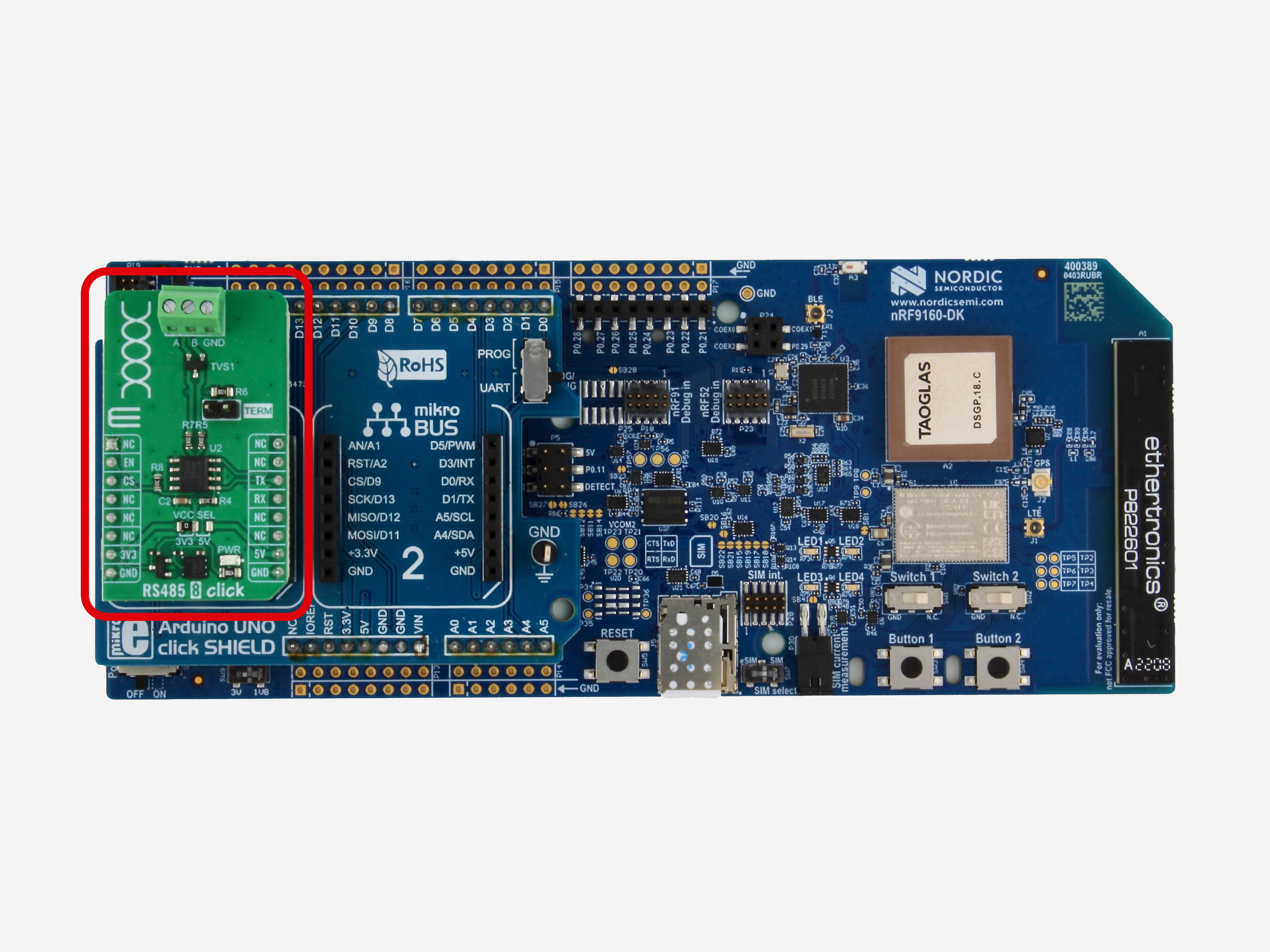
Step 4 - Install Click sensor board
-
Install the RS485 8 Click board into the mikroBUS host socket labeled "1".
-
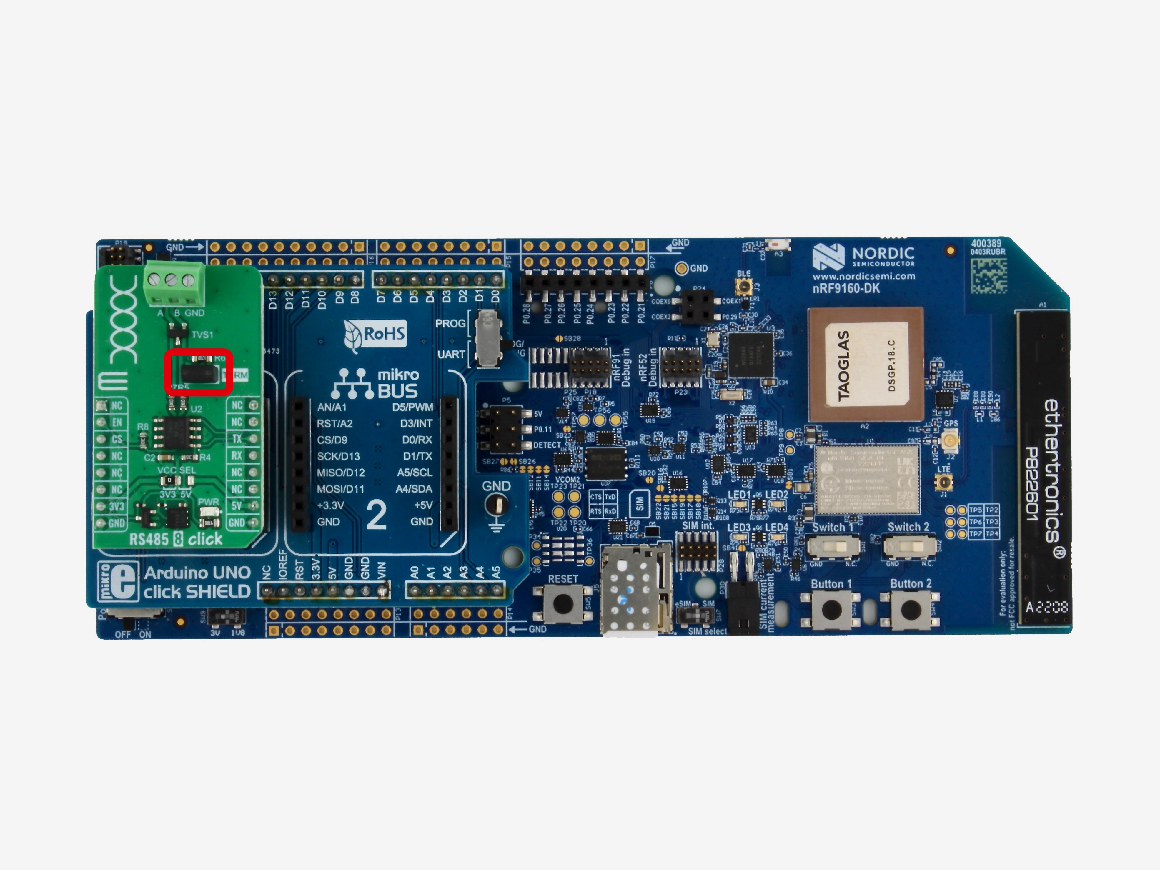
Install the 2-position shunt jumper onto the header labeled "TERM" on the RS485 8 Click board.
Step 5 - Connect Vibration Sensor and Power Supply
-
Insert the flying lead bare wires from the Banner
MQDC1-501.5cable into the terminal block connector on the RS485 8 Click board as shown in the table below:MQDC1-501.5Flying Lead Bare Wire ColorRS485 8 Click Terminal Block Label Blue GND Black B White A Exposed +24VClip (or insulate) the unused brown (+24V) and grey (not used) flying lead bare wires on the Banner
MQDC1-501.5cable, leaving only the blue, black, and white wires exposed.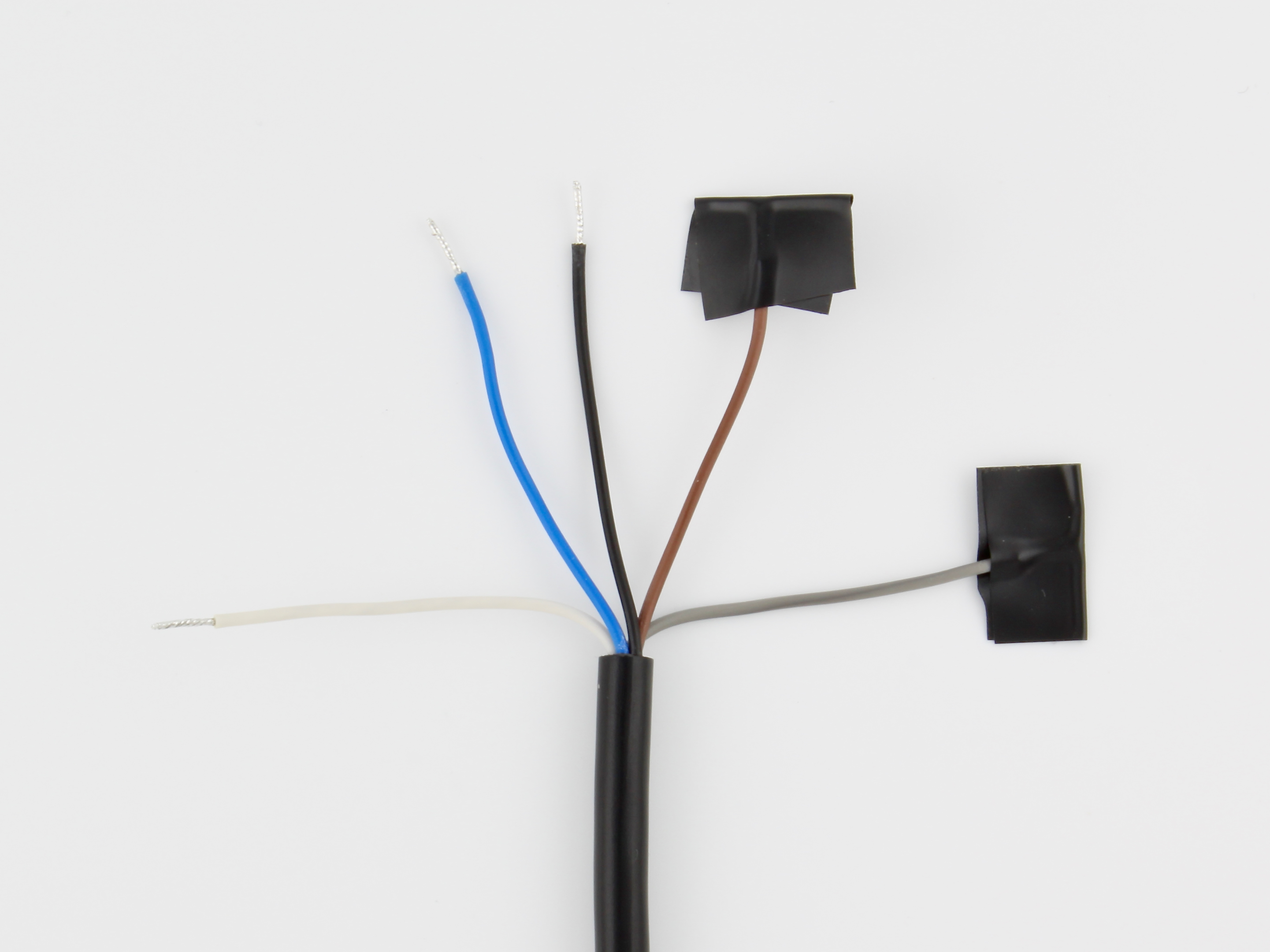
-
Screw the M12 female connector of the Banner
MQDC1-501.5cable into one of the M12 male "branch" connectors on the BannerCSB-M1251FM1251Msplitter cable assembly.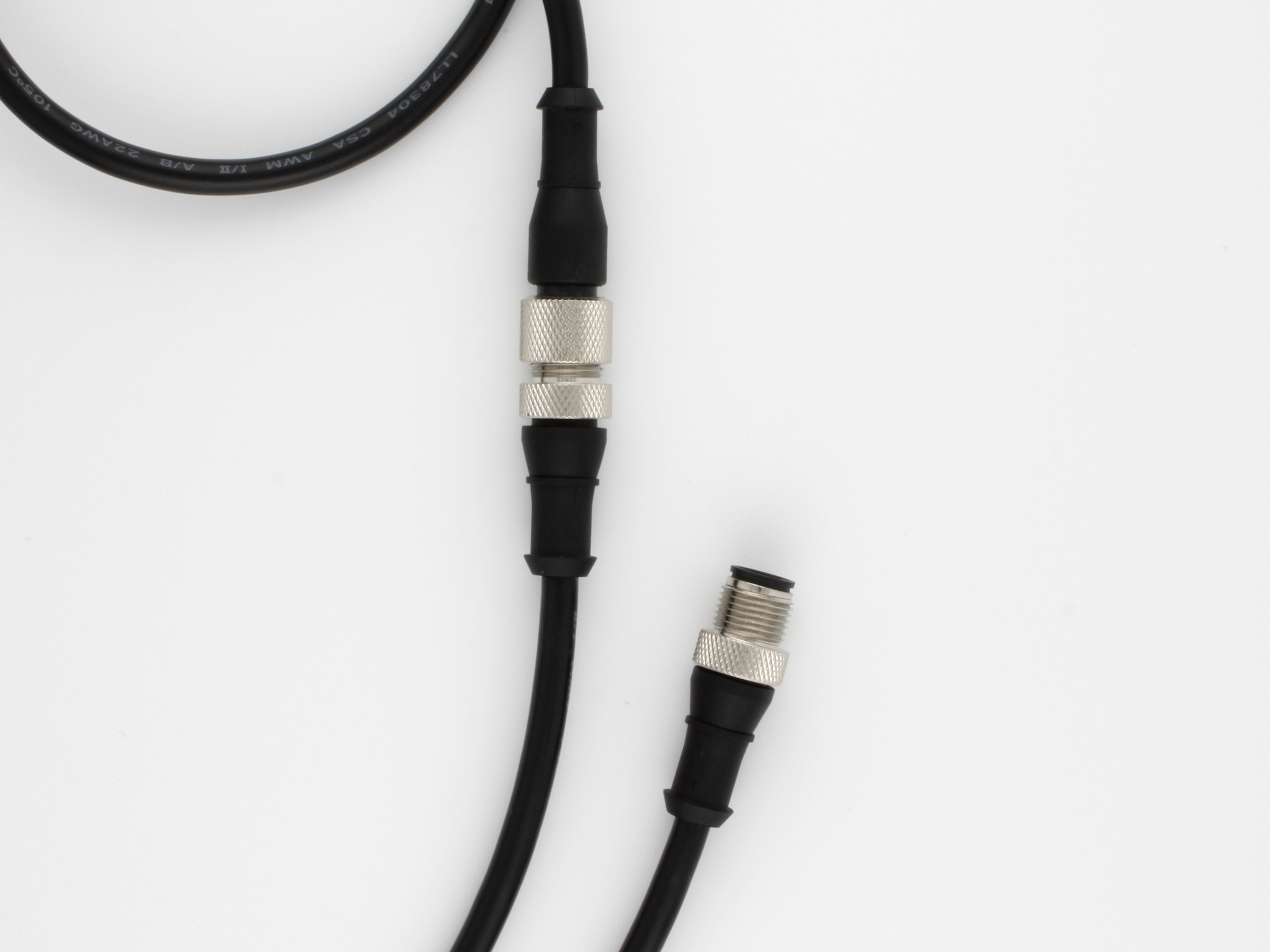
-
Screw the M12 female connector of the Banner
PSW-24-2power supply into the other M12 male "branch" connector on the BannerCSB-M1251FM1251Msplitter cable assembly.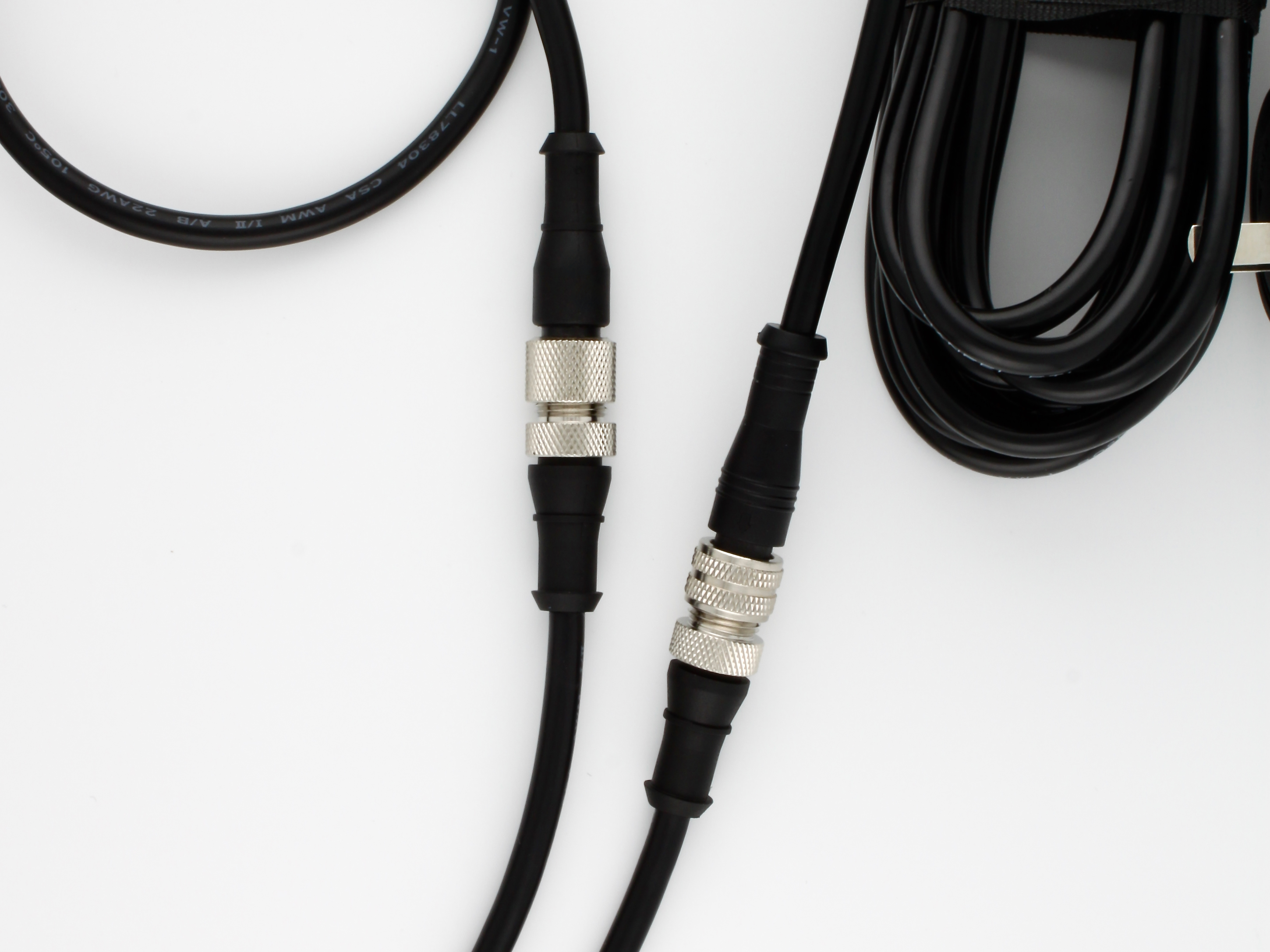
-
Screw the M12 male connector of the Banner
QM30VT2vibration sensor into the M12 female "trunk" connector on the BannerCSB-M1251FM1251Msplitter cable assembly.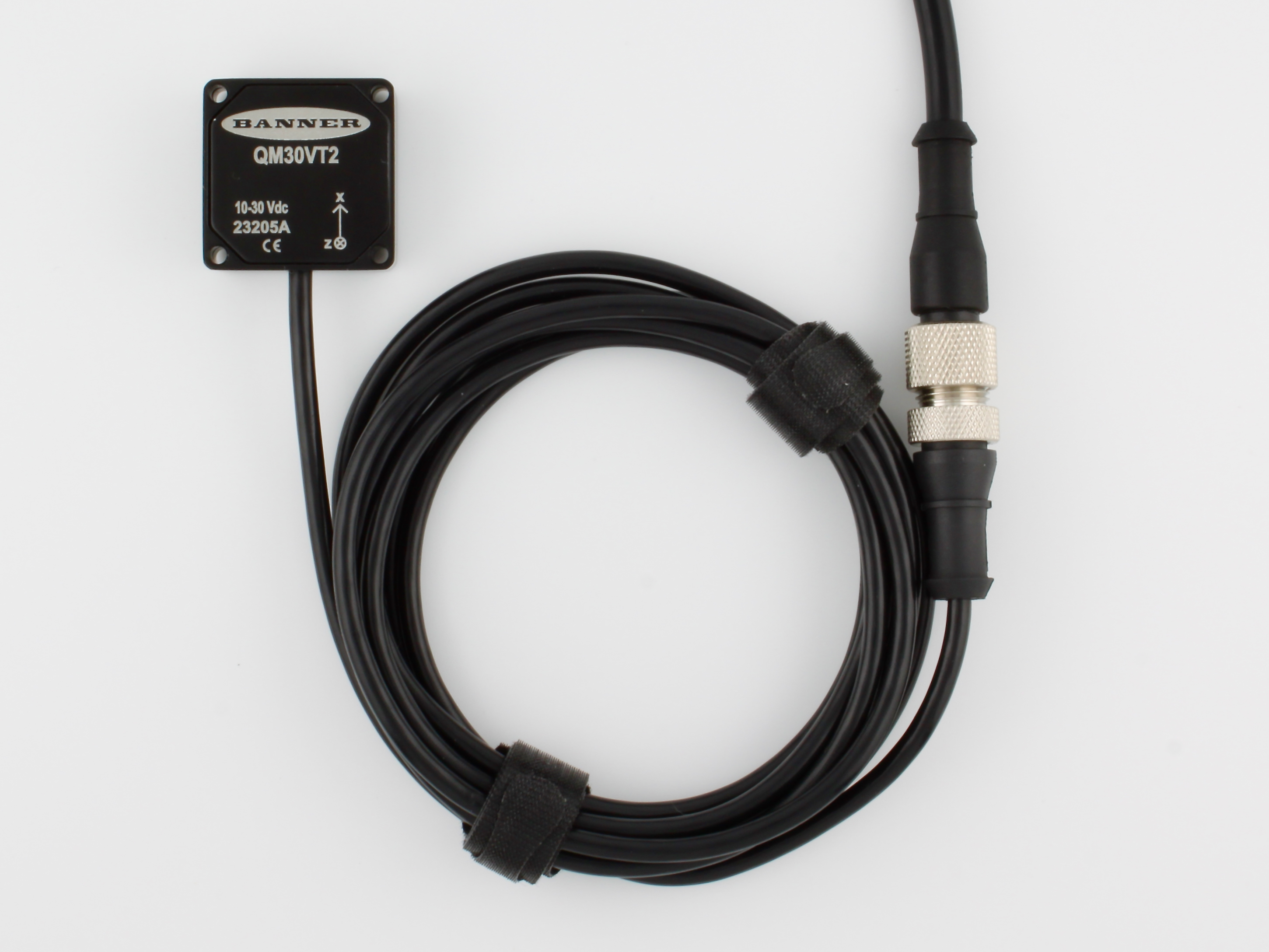
-
The final result should look like this:
Flash the firmware
The firmware source code and pre-built firmware images for this reference design are available on GitHub under a permissive Apache-2.0 license.
The Modbus Vibration Monitor firmware is based on the Golioth Reference Design Template. Changes from the upstream template are periodically pulled into new releases of this firmware. Check out the firmware CHANGELOG for a detailed list of changes included in each release.
Flash the pre-built firmware image
We recommend getting started by flashing the latest pre-built release firmware image. These release images have been tested by the Golioth team and are the quickest way to verify that the hardware is working correctly.
Step 1 - Download the pre-built firmware image
Download the latest golioth-reference-design-modbus-vibration-monitor_v1.0.0_nrf9160dk_nrf9160_ns_full.hex firmware image file from:
Step 2 - Install nRF Connect for Desktop
We recommend using the nRF Connect for Desktop application to flash the pre-built firmware image to the board.
You can download the latest version for Windows, Mac, and Linux from the Nordic website (make sure to choose your operating system from the dropdown):
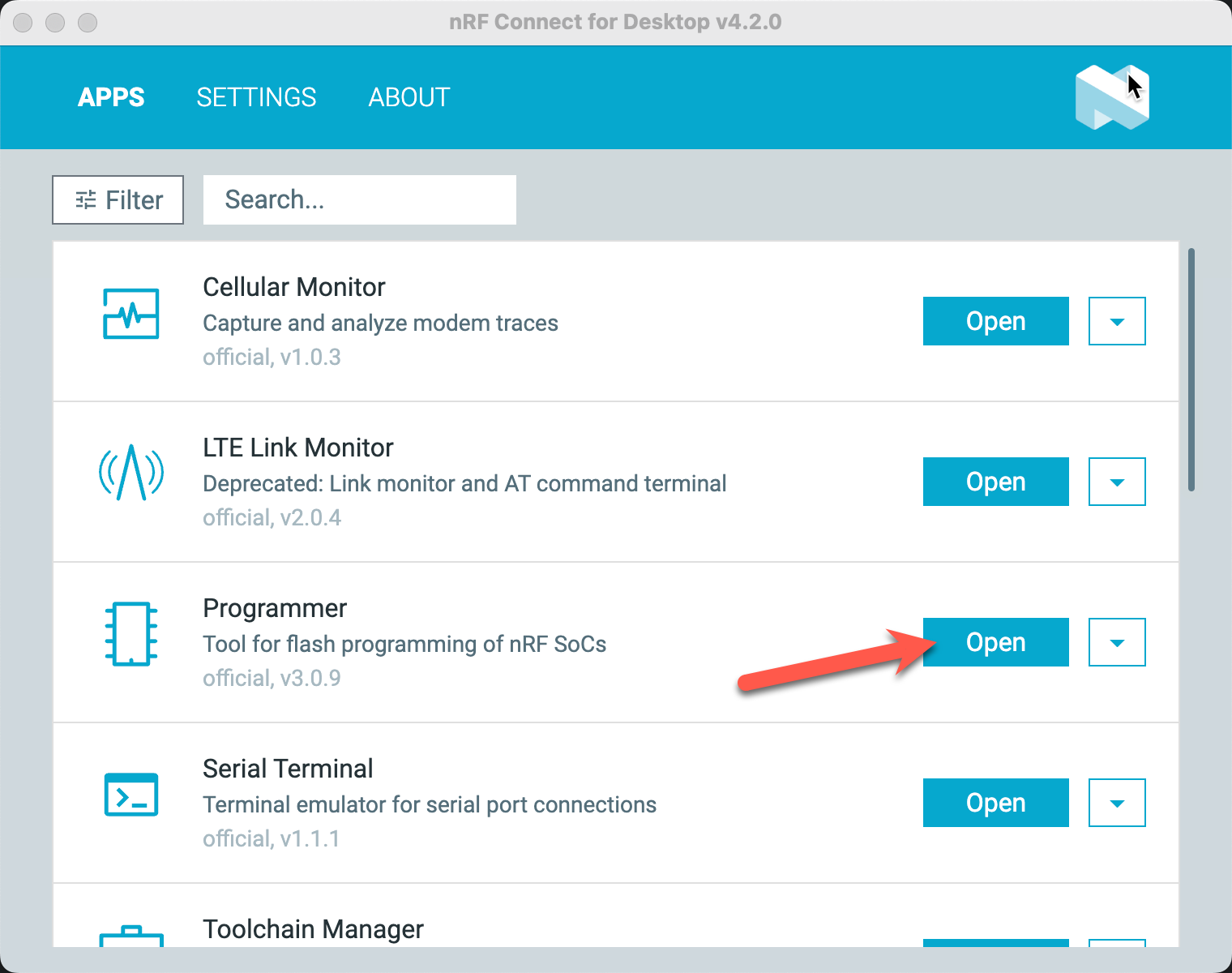
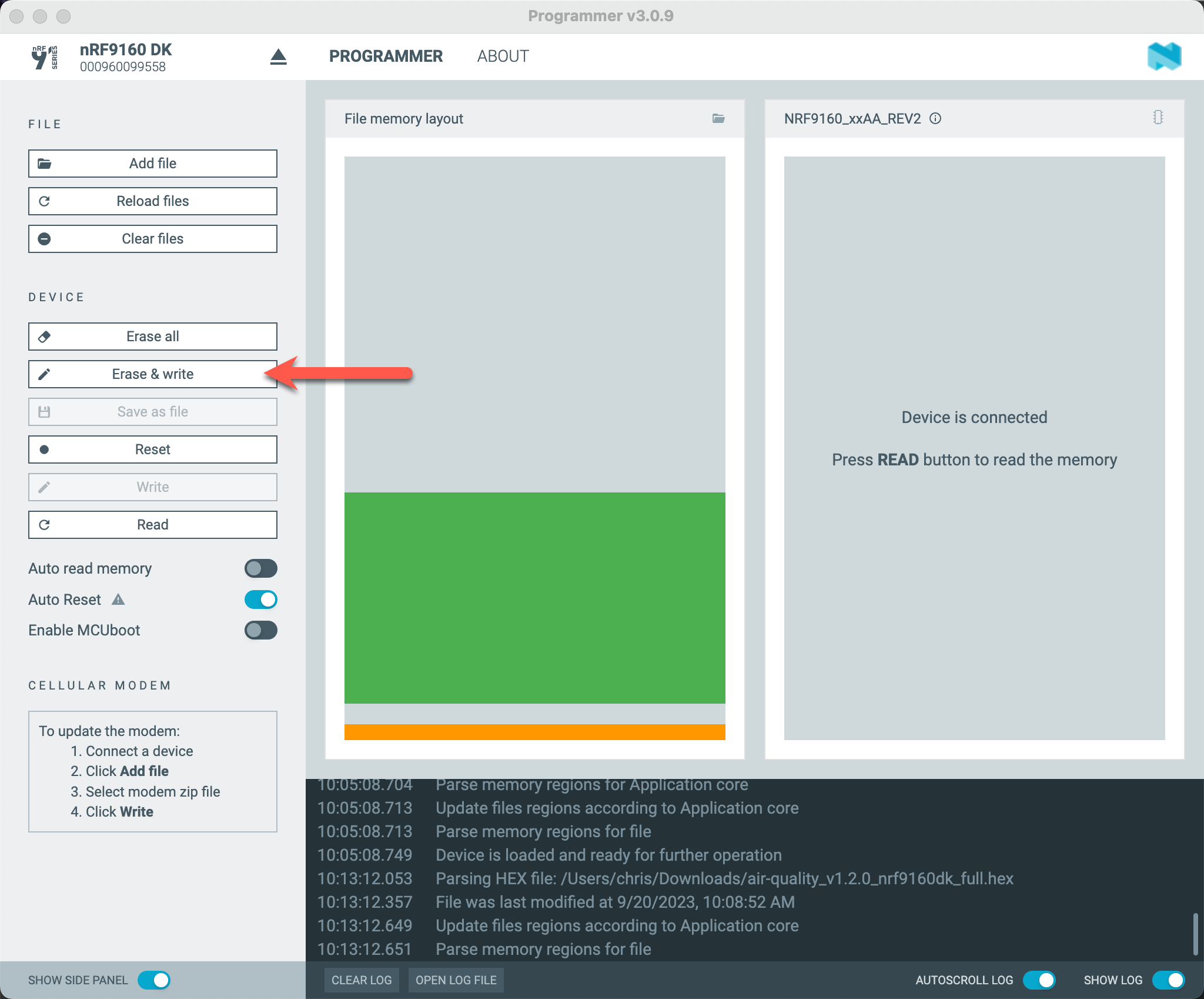
Step 3 - Flash firmware with the Programmer app
After installing nRF Connect for Desktop, open the Programmer app:
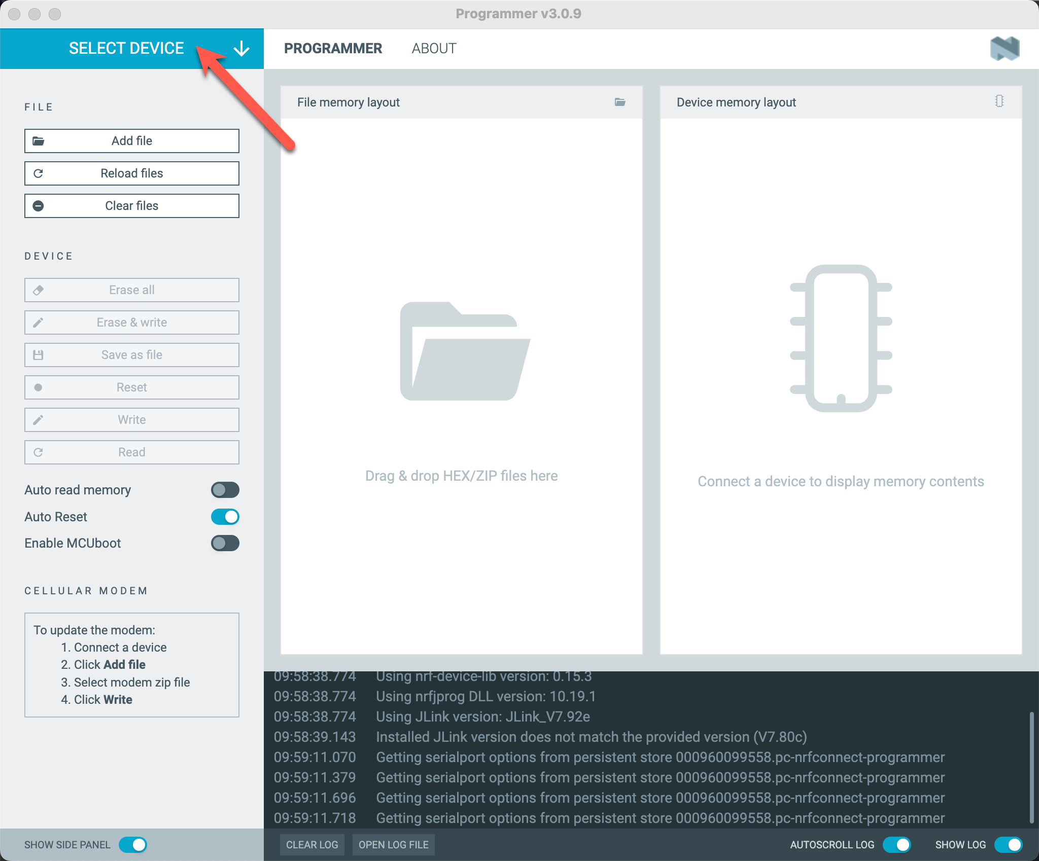
Click on "Select Device" to show the list of available boards:
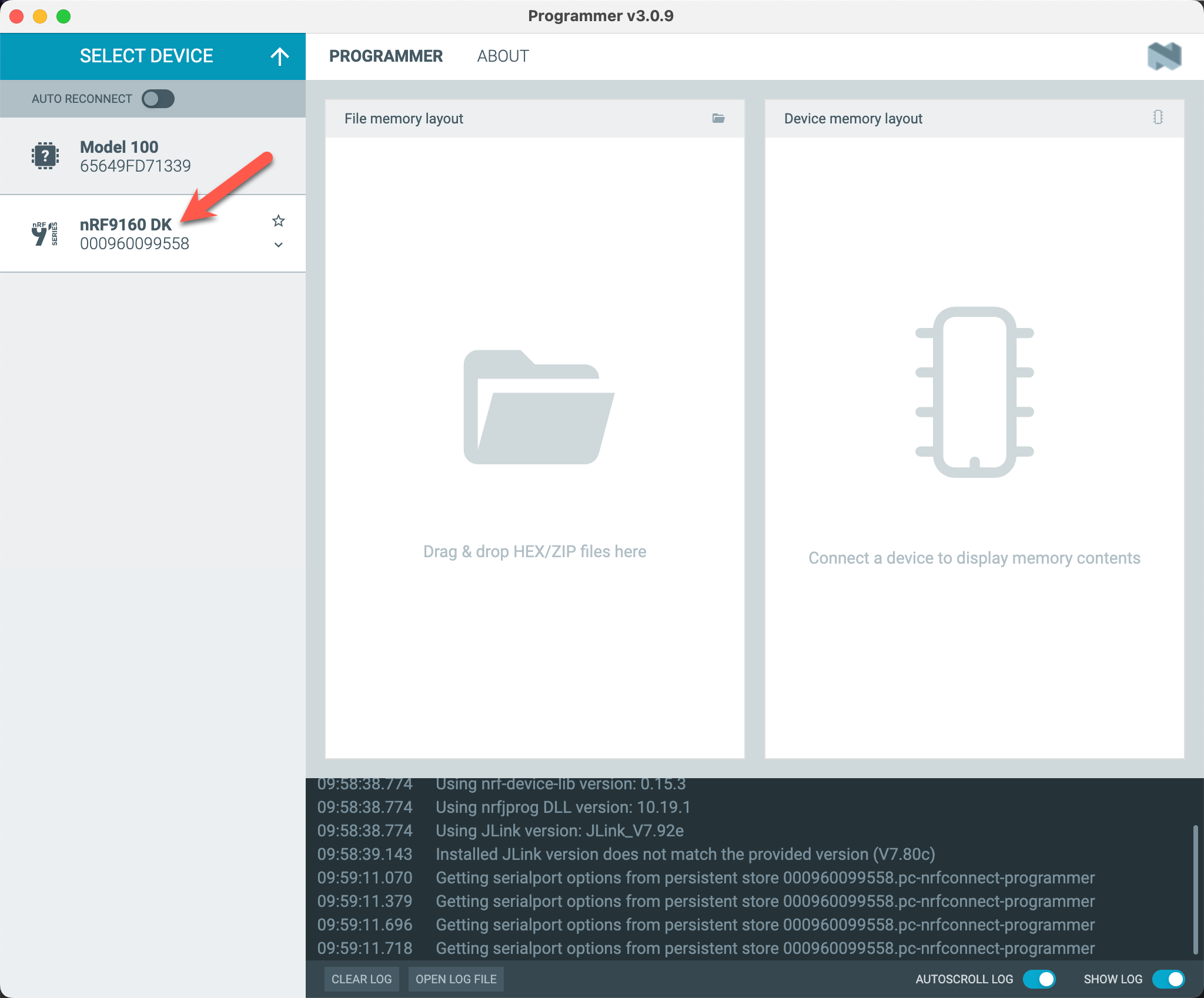
Select the board used in your follow-along hardware:
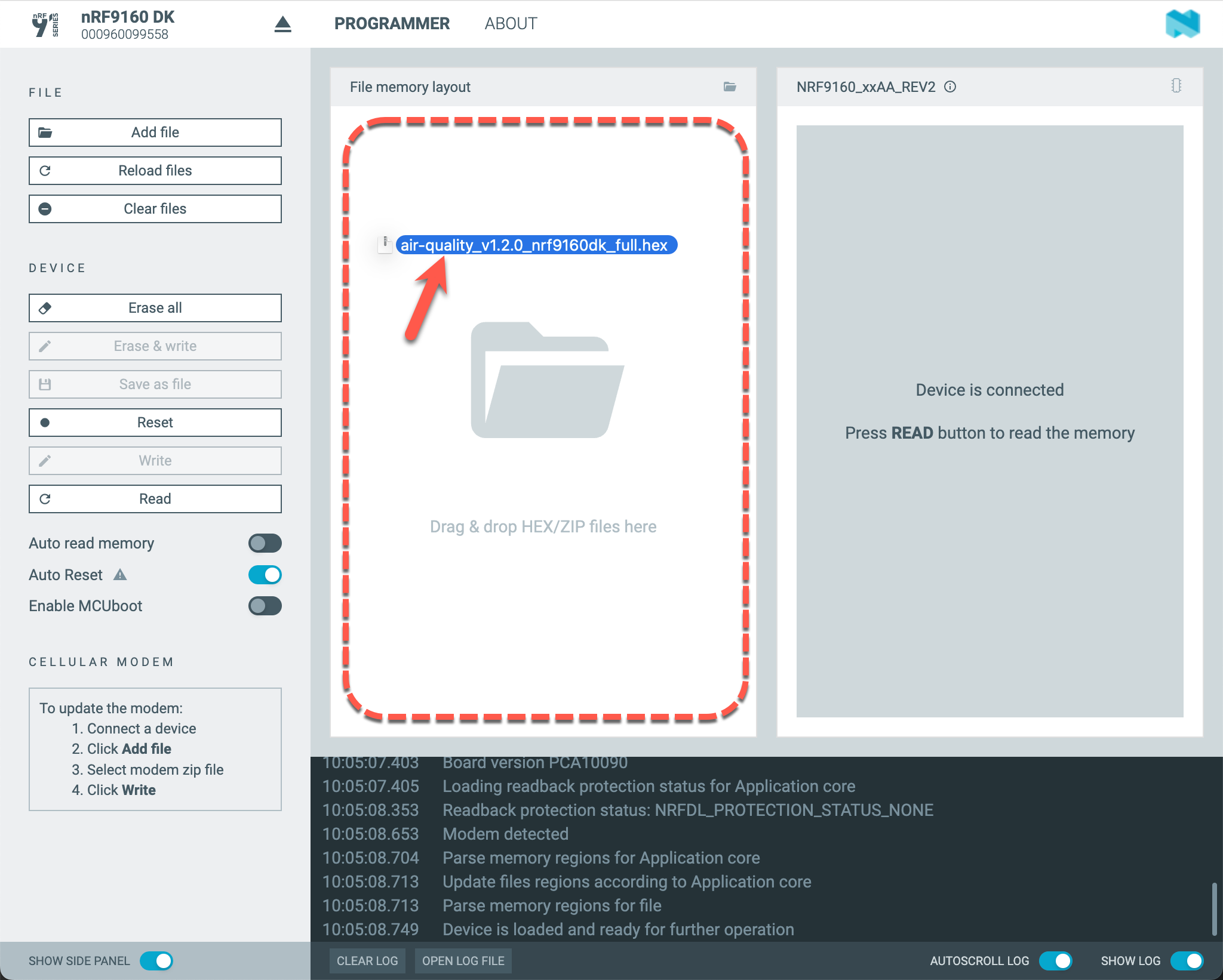
Drag & Drop the golioth-reference-design-modbus-vibration-monitor_v1.0.0_nrf9160dk_nrf9160_ns_full.hex file onto the "File memory layout" pane:
Click "Erase & Write" to program the firmware image into the device:
Step 4 - Verify firmware with the Serial Terminal app
If the firmware was programmed successfully, you can verify the firmware version printed on the serial terminal.
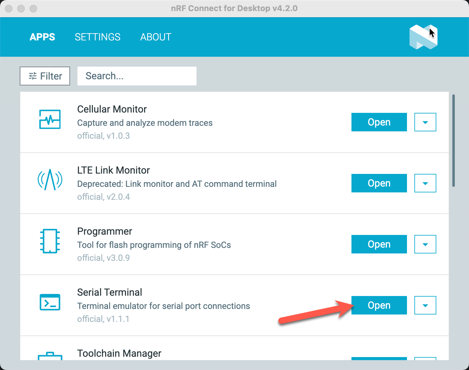
Open the nRF Connect for Desktop Serial Terminal app:
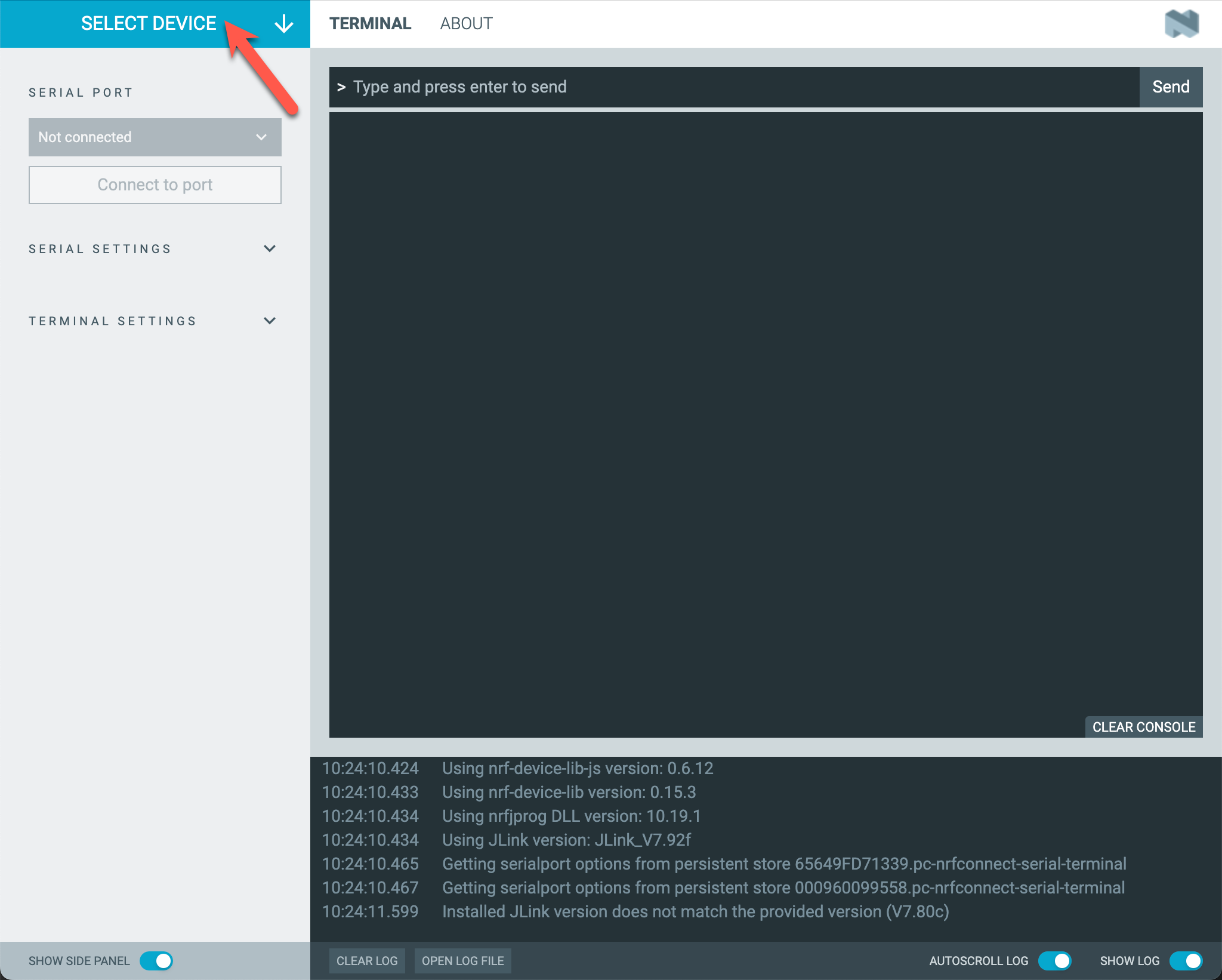
Click on "Select Device" to show the list of available boards:
Select the board used in your follow-along hardware:
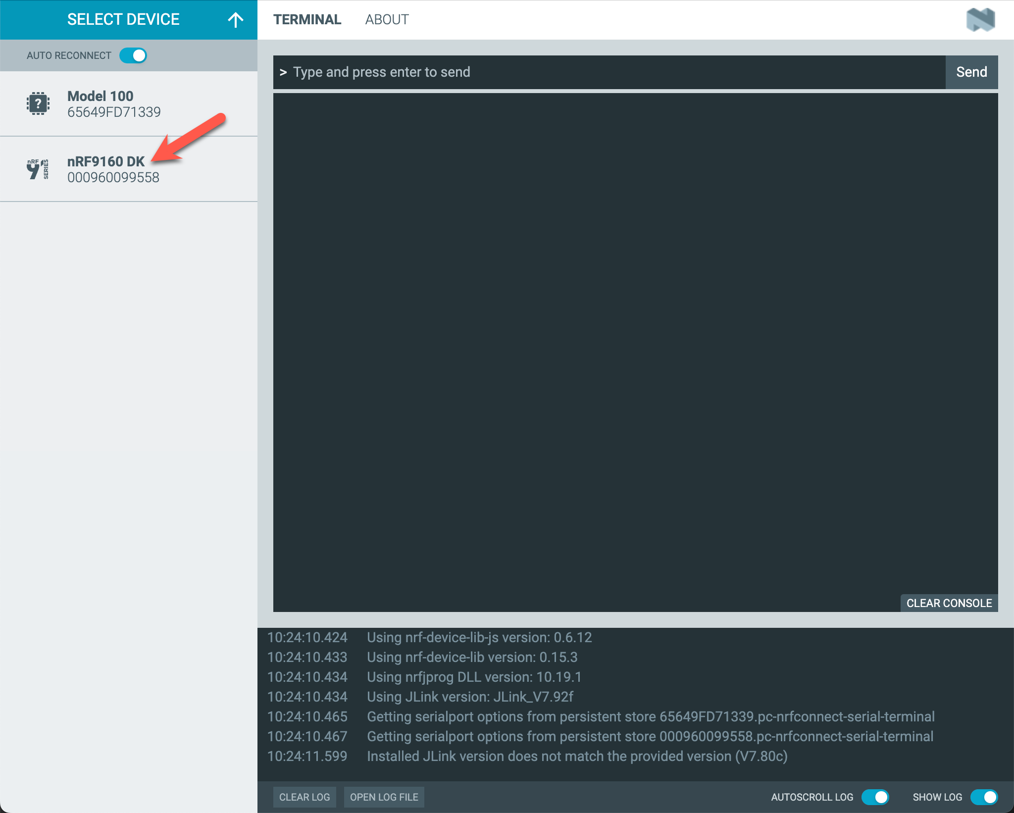
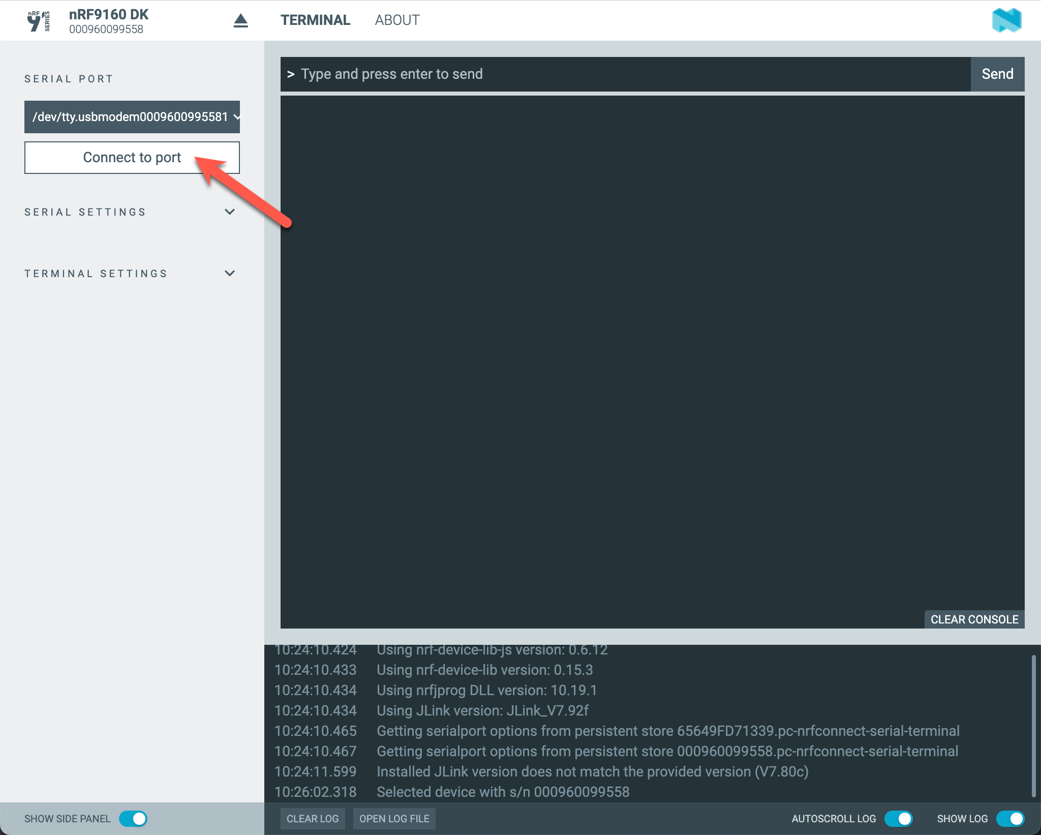
Click "Connect to port":
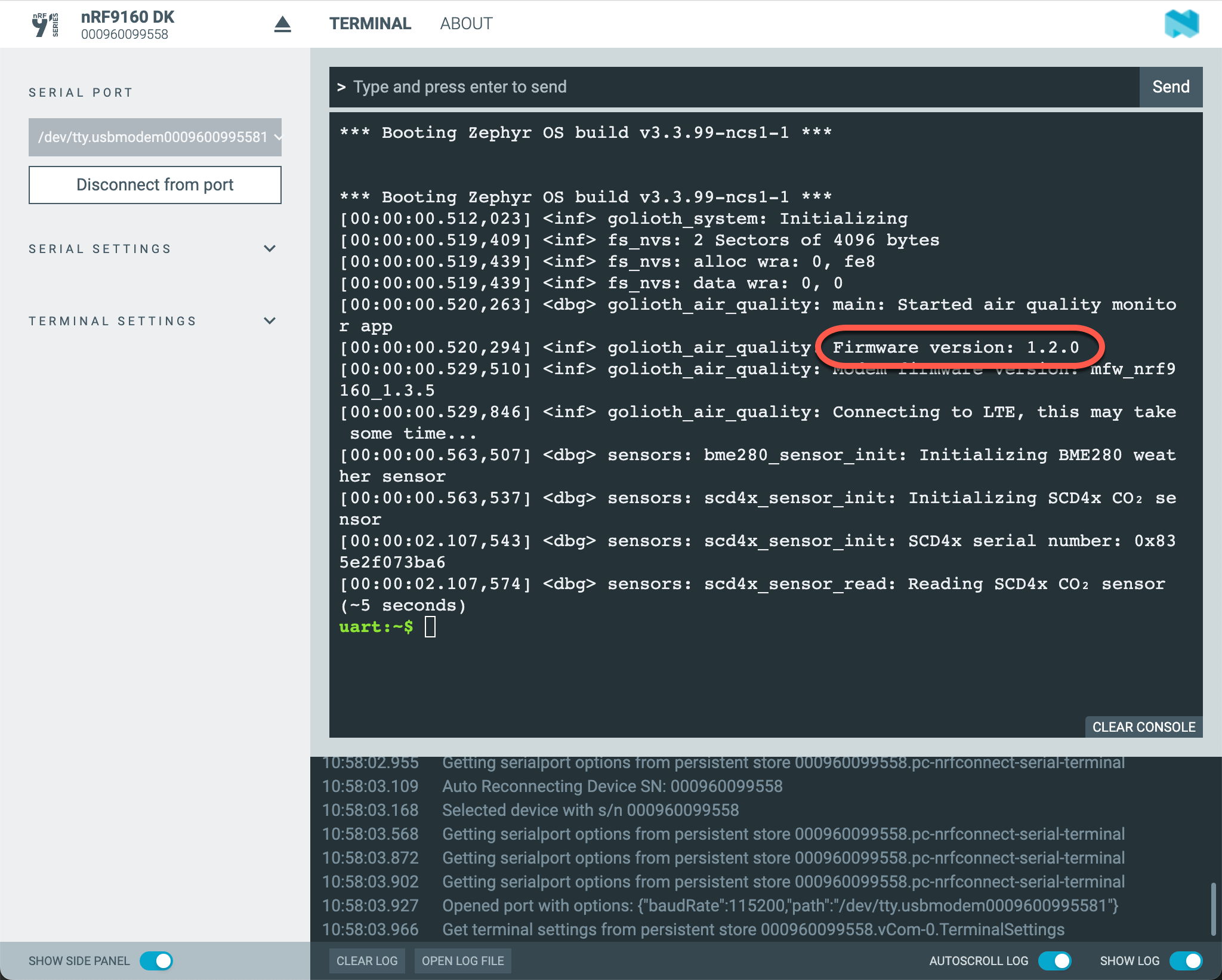
You should see the firmware version printed in the log output (if you connected after the log message was printed, press the RESET button on the board):
Connect to Golioth
In this section you will learn how to connect the follow-along hardware to the Golioth Cloud.
Register & Log In
The Golioth Console provides a web-based dashboard for registering & managing your devices.
To get started, log in to the Golioth Console. If you have not already signed up for a Golioth account, choose "Sign Up" to register for a new account first.
Register the Device
The Quick Start Wizard will guide you through the process of creating your first Project and registering your first device.
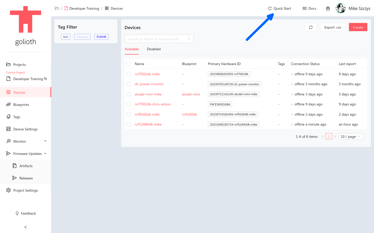
Launch the Wizard by clicking on the "Quick Start" button in the top right of the console window.
If you previously registered for Golioth, you may have already created a project and registered a device the first time you used the Quick Start Wizard. Feel free to skip this section and register a new device in your existing project instead of creating a new project via the Quick Start Wizard.
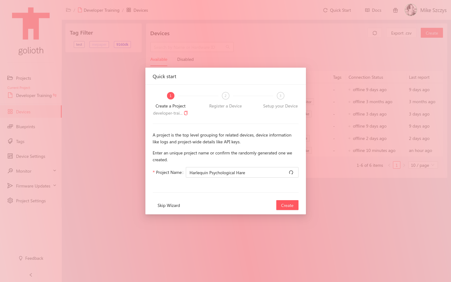
Step 1 - Create a Project
All devices must belong to a Project. Before you can register the device you must create a Project in the Golioth Console.
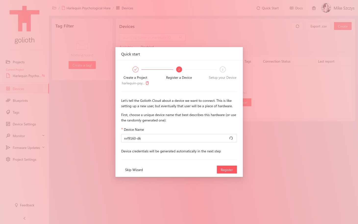
Step 2 - Register a Device
Choose a name for the device or use the randomly generated one.
Step 3 - Setup your Device
The Quick Start Wizard will automatically generate pre-shared key credentials for the device that was just registered.
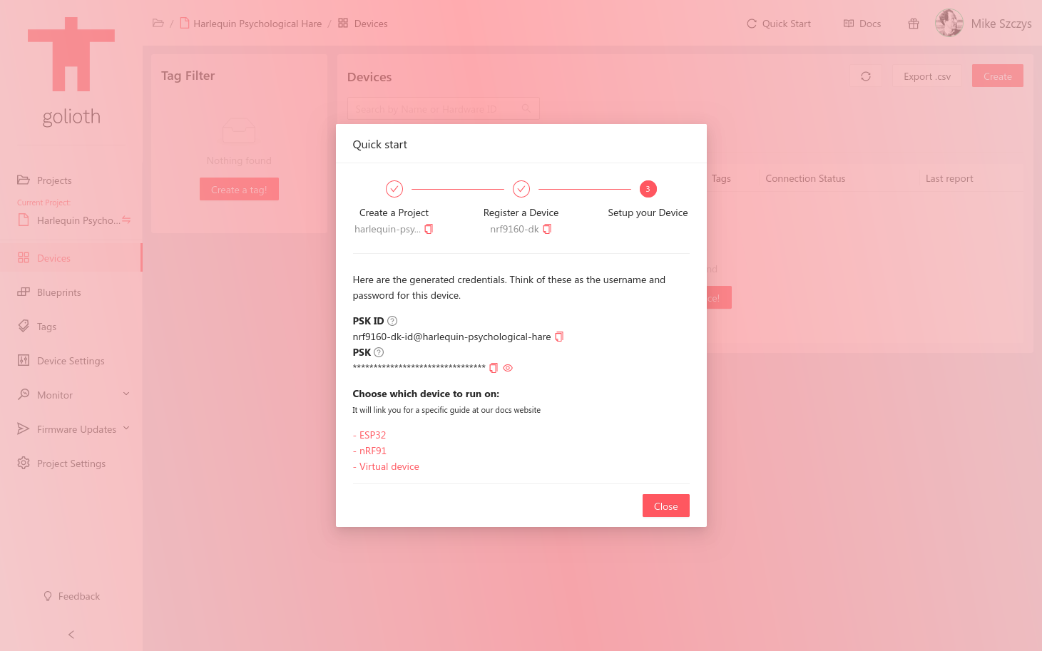
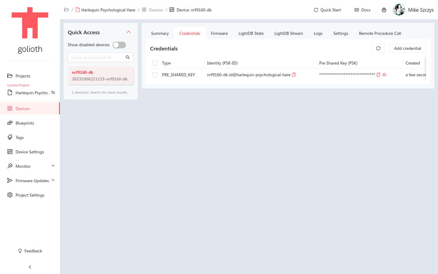
After you click "Close" in the Quick Start Wizard, you can always find these credentials again on the device's "Credentials" tab.
Provision the Device
Now that the device is registered in the Golioth Console, the device hardware needs to be provisioned with the pre-shared key that was generated in the previous step.
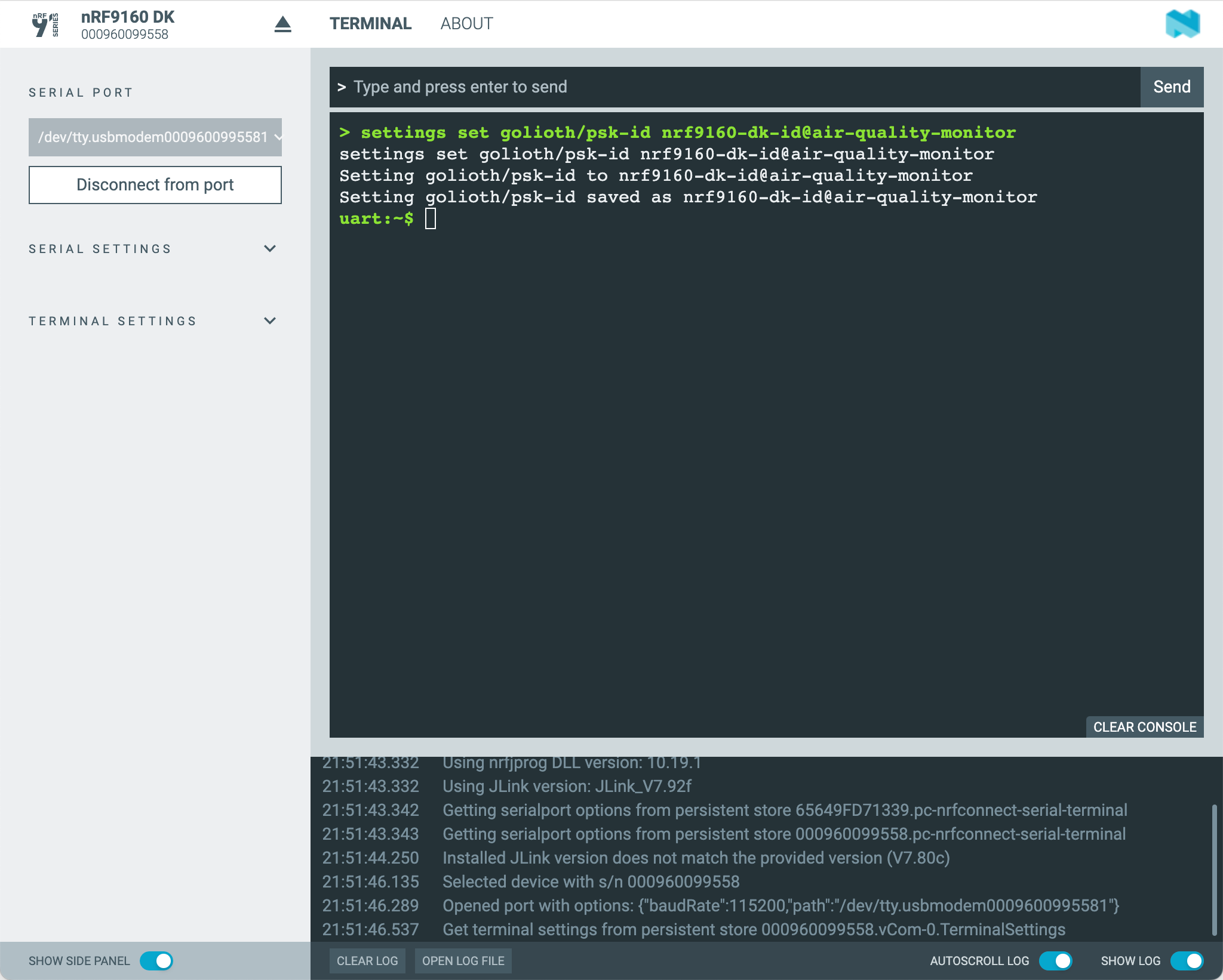
In the nRF Connect for Desktop Serial Terminal (or your preferred serial terminal application), set the following values using the device shell:
uart:~$ settings set golioth/psk-id <my-psk-id@my-project>
uart:~$ settings set golioth/psk <my-psk>
uart:~$ kernel reboot cold
For example, setting the golioth/psk-id should look like this:
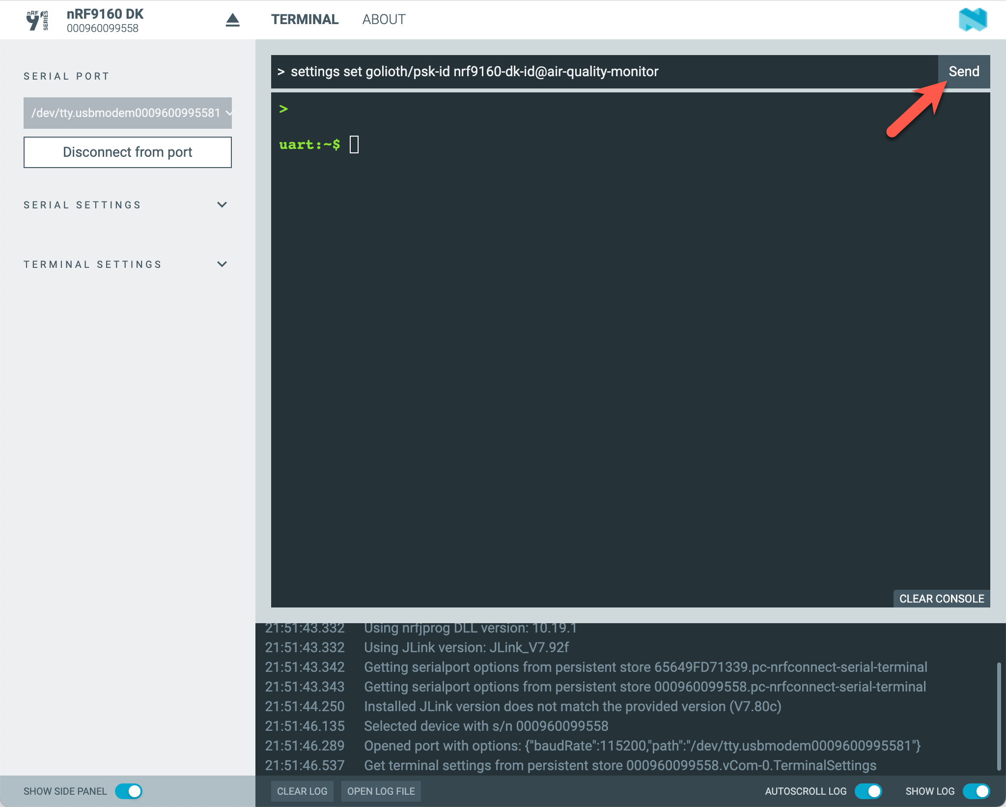
After clicking the "Send" button, you should see the command output showing that the PSK-ID was saved to the device's non-volatile storage:
Verify the Device Connection
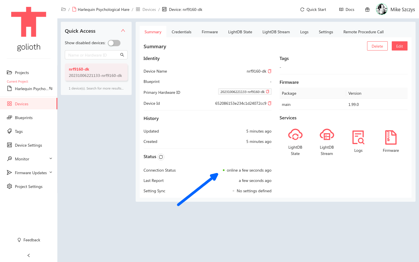
Once the device has rebooted, the firmware should automatically connect to the Golioth Cloud.
Once the device has connected, you should see the device "Connection Status" change to "online".
If you click on the device's "LightDB Stream" tab, you should see data streaming in from the device.
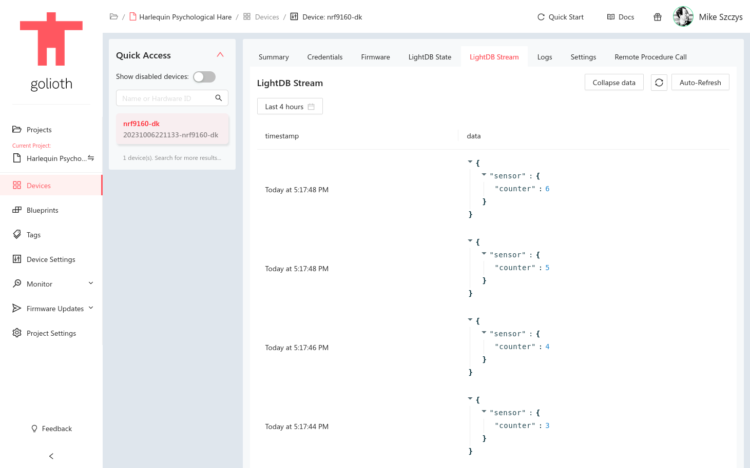
Congratulations, you have successfully connected your follow-along hardware to the Golioth Cloud!
Next Steps
Interact using the Golioth Console
Now that your device is connected to the Golioth Cloud, you can explore the other Golioth features used by the Modbus Vibration Monitor. Information for working with OTA Firmware Updates, Device Settings, RPCs, Logs, and example output for time-series Stream data and LightDB State data are available in the Golioth Features section of the firmware repository.
Some ideas:
- Check out the "Logs" tab to see real-time log messages streaming from the device.
- Click the "LightDB Stream" tab and use the refresh button in the upper right to see time-series data arriving to the cloud from your device.
- Navigate to the "Remote Procedure Call" tab and call the
get_network_infomethod to query and return detailed information about the device's network connection.
Compile a custom firmware image
The source code for the pre-built firmware image can be customized for your specific application. For detailed instructions on how to build the reference design firmware used in this guide, see the README in the firmware GitHub repo.
If you're brand new to building firmware with Zephyr, we provide free online developer training.